Lubrication and Compressor Life


A wise engineer once told me that “lubrication is the secret to life” and that is certainly the case when it comes to AC system compressors.  Design and development engineers strive to find the proper balance between adequate oil charge to lubricate the internals of a compressor and having too much oil in the system.   Too much oil will degrade AC system performance by inhibiting heat transfer in the condenser and evaporator.   Overcharging a system with oil can also cause problems with variable displacement compressors that use mechanical control valves.   When it comes to oil in an AC system more is not better.

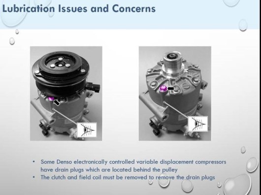
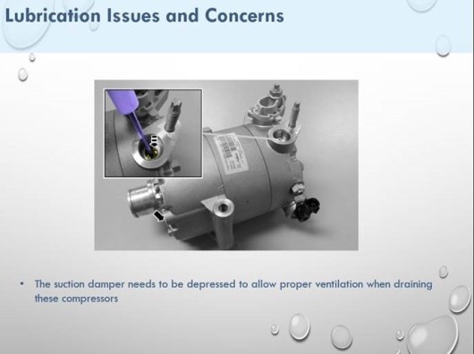
My colleague, Richard Hawkins, from the 1-800-Radiator & A/C technical support group reviewed the topic of “A/C System Lubrication System Issues & Concerns” at the 2020 MACS Conference in Nashville, TN.   Some lubrication and service issues are summarized in these slides from his presentation at the conference.

slide 1

slide 2

slide 3

slide 4

slide 5


MACS members can find Richard’s entire presentation at:

https://www.macsw.org/web/MACS/MACS_Member_Only_Content/Training_Event_Archives


2018 Refrigerant Mandate


As of January 1, 2018 the EPA added new regulations in regards to the purchase of refrigerant.  See the EPA website to read firsthand the changes and requirements.

https://www.epa.gov/section608/refrigerant-sales-restriction

For Large Cylinders – over 10 pounds – the seller must keep an invoice listing the name, date, and quantity of refrigerant sold. The seller must see a section 608 or 609 technician certification card. If the purchaser is acquiring the product on behalf of a shop, then evidence must be provided that at least one of the technicians in that shop is certified. The seller must keep a copy of the purchaser’s technical certificate on file and all records must be kept for a minimum of three years.


For Small Cans – to the general public, two pounds or less of R134a – There is no restriction on sale of cans less than two pounds, but the can should be manufactured with self-sealing valve.

For technicians who have completed section 608 or 609 certifications, the certification does not expire. For technicians who have misplaced their credentials and require a new copy, please contact the issuing company (eg: MACS) for a replacement. A processing fee may apply. For technicians who require certification, please visit the MACS website (www.macsw.org) for section 609 certification including training on handling the new refrigerant R-1234yf. The training and certification test cost $20.00.

Rear Air Conditioning Elimination


Many SUV’s and vans have standard or optional rear air conditioning systems that rely on underbody lines to move refrigerant to and from the rear evaporator.   Often these lines will fail due to pitting corrosion while operating in northern climates that use salt for deicing the roads.   The cost to replace a line to make the rear AC system option functional may be more than a customer can justify .   A less costly option is to eliminate the rear AC circuit completely. Once the rear circuit is eliminated, and the front part of the system is confirmed to be leak free, the system can be appropriately recharged with refrigerant and oil.

To eliminate the rear AC lines one should terminate each line as close to the front of the vehicle as possible thereby reducing the possibility of leaks from any remaining line sections.   In many cases this can be accomplished using cap off kits designed to interface with the original equipment connections at the front connection “Y” sections.   These kits are very reliable and easy to install since they do not require any cutting or welding of the lines that are being terminated. Cap-off-kits for many vehicles are offered by Auto Air and Accessories Inc. of Blaine MN.  One of the most popular cap-off kits illustrated below is often used as an alternative to repairing leaks at the rear evaporator on Chrysler mini-vans.

img_1584


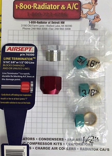
A second option for eliminating the rear AC circuit is to cut the lines at the damaged point or just behind the front “Y” joint connection and then install line terminators.   A popular type of terminator, (Smart Splice Line TerminatorTM by Airsept), sold in both English and metric lines sizes, incorporates specially designed compression fittings.   When using these types of terminators one should install them as close to the front of the vehicle as possible to reduce refrigerant and oil pooling in the rear AC lines.  One needs to accurately measure both the liquid and suction line sizes before selecting the mating fittings.   Sometimes one of the lines will be an English size and the other will be a metric size and it is important to only use the fittings specifically designed for the lines being terminated.   A typical terminator kit is illustrated in the following photo.  One will need a terminator for the liquid and another for the suction line.

img_1585


A final option is to cut the lines, flatten the ends and TIG weld them closed.   This option is the least desirable for most shops because they would need to out-source the TIG welding.

Regardless of which of the above options is selected, the installer must consider the reduced system volume and compensate by reducing the refrigerant and oil charge.   If all of the rear circuit has been eliminated due to the location of the line terminations, then the manufacturer’s specifications for a front AC only system would provide a close approximation for the recharge specifications.   And as with all AC repairs, one should check for leaks after the system has been in use for a short period of time and again annually to assure that the system will continue to meet the customer’s expectations for comfort and reliability.


AC System Driers


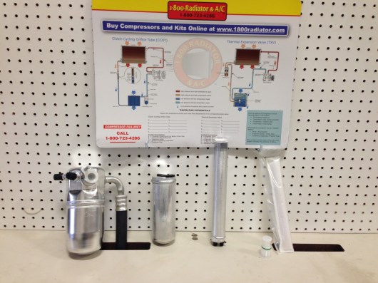
There are four main types of driers found in AC systems.   They can be identified based on their location in the system.

  1. Accumulator – located in the circuit between the evaporator and the compressor in a system using an orifice tube as the expansion device – a typical cycling clutch orifice tube system (CCOT).
  2. Receiver – located in the circuit between the condenser and the thermal expansion valve (TXV).
  3. Sub-cool Receiver – located between the second to last pass and the last pass in a parallel flow condenser.
  4. Desiccant Bag or Cartridge – same location as #3 but used to service parallel flow condensers with receiver tanks that are brazed permanently to the condenser.


IMG_1406

Accumulator                 Receiver             Sub-cool Receiver           Desiccant Bag


In order to properly service an AC system and return it to near factory condition each component should be cleaned of all residual oil and debris before re-assembly, evacuation, and recharge.   Since it is impossible to clean a drier one should always replace them.

Driers have a limited capacity for absorbing and retaining moisture and once they are saturated they cannot protect the refrigerant circuit. Most driers also incorporate a filter screen which traps debris from other components such as normal wear particles from the internal parts of the compressor.  

Another reason for replacing the drier when a system is serviced is to remove contaminated refrigerant oil they have collected.   PAG oil that is saturated with moisture or other contaminants will not provide proper lubrication for the compressor.

In actual practice drier types 3 & 4 are always used in systems which have parallel flow condensers (PFC).   Since these condensers cannot be cleaned they often require replacement and the new condenser will generally be supplied with an attached drier.   For more information about these types of condensers please refer to the tech tip titled “Condensers with Integrated Receiver Driers”.


http://macsworldwide.wordpress.com/


http://macsworldwide.wordpress.com/.

Condensers with Integrated Receiver Driers


Our last tech tip reviewed the evolution of condenser designs and discussed why parallel flow condensers trap debris from a worn or failed compressor.  Severe contamination of a parallel flow condenser can reduce the capacity of the condenser and restrict oil circulation that is vital to the life of the compressor.  In this tip we will review some of the considerations when servicing the attached/integrated receiver driers which are now common place in both domestic and import applications.

All system applications which use a thermal expansion valve (TXV) to control refrigerant pressure in the evaporator also incorporate a receiver drier in the circuit.  In an effort to reduce space and mass while providing improved performance, newer sub-cool condenser designs have integrated receiver driers which are located between the last two passes of the condenser.  Some sub-cool designs have detachable receiver driers which can be replaced as a component.  See photos below.

 Condensers with detachable Receiver Drier

Other designs have receiver driers that cannot be detached and are serviced by removing a plug from the lower end of the receiver.  Service kits include new a new plug, desiccant bag, and filter.  See photos below.

Condenser with serviceable Receiver Driers


Regardless of whether the receiver drier is detachable or serviceable, in most applications the condenser must be removed from the vehicle to service the receiver drier.  If the condenser is mounted to the radiator it may also be necessary to remove the cooling module and, in severe cases, bumper covers and grills have to be removed to provide access to service the condenser.  

Furthermore, as discussed in our last tech tip, parallel flow condensers cannot be cleaned effectively.  If the condenser is a sub-cool design like those shown in the above photos, a new replacement condenser will generally include a new receiver drier as part of the assembly.  Because of the probability of condenser contamination and the part/labor cost related to servicing an integrated receiver drier, replacement of the condenser/receiver drier assembly is the best overall repair strategy whenever a new compressor is installed.

Condenser Contamination


We all understand that condenser performance is affected when air flow is restricted by dirt, grass, salt, and other contaminants plugging the air side of the condenser.   Debris plugging the air side of a condenser causes the system to operate at higher pressures and temperatures which can affect not only comfort but can lead to premature compressor failure.  On the other hand, it is just as important that the refrigerant side of a condenser remains clean and unobstructed if optimal performance and reliability is to be achieved.

When a compressor fails the debris from the compressor as well as the contaminated oil must be cleaned out of the condenser and other components to assure a trouble free – reliable repair.  Because the refrigerant side of newer condenser types cannot be cleaned effectively they must often be replaced as part of the A/C system repair.

Most automobiles on the road today use R134a as the refrigerant in their A/C system.  When R134a was introduced as a replacement for R12, higher capacity – more efficient condensers were needed to compensate for the differences in the thermodynamic properties of the new refrigerant.  Since the space available for the condenser is limited by the layout of the engine cooling compartment, engineers had to find ways to increase capacity without increasing the overall size of the condensers.  

The requirement for increased heat transfer capacity led to application of new styles of condensers to replace the conventional tube and fin and serpentine designs that were being used by the vehicle manufacturers.  The photo below shows cross sections of four types of condensers starting with a conventional tube and fin design on the left, followed by another tube and fin variation, then a serpentine tube design, and finally a parallel flow condenser.  These cross sections illustrate how individual refrigerant flow passage size has become progressively smaller with each evolution of condenser designs. 


                  Tube&Fin      6mm Tube&Fin   Serpentine     Parallel Flow

The early generations of parallel flow condensers have now been superseded by new designs with even smaller refrigerant flow passages.  A tube from one of the most advanced designs is illustrated in the photo below.


Micro – port condenser tube

The tiny flow passages in a micro – port tube can be obstructed even more easily by contamination from a worn or failed compressor.  Some passes in the condenser have as few as three of these tubes arranged in a parallel layout between the opposite ends of the condensers.  If one of these tubes becomes obstructed the overall capacity of the condenser is degraded and oil circulation vital to compressor life is compromised.

Condenser evolution did not stop with the introduction of the parallel flow condenser.  The desire to reduce refrigerant charge volume, while further reducing the space and mass requirements of the A/C system, prompted the development of condensers with integrated receiver – driers and sub-cooling sections.  In this arrangement a section of the condenser is reserved for sub-cooling the liquid refrigerant as it exits the receiver-drier.  We will provide more details about the function and benefit of the “sub-cool” type condenser in our next tech tip.

Meanwhile, the key point to remember is that all parallel flow condensers trap material and contaminated oil that is discharged from a failed compressor.  When this contamination blocks the small flow passages in the condenser, cooling capacity is reduced leading to higher system temperatures and pressures.  Severe cases of contamination will obstruct oil flow thus preventing proper lubrication of the compressor.  If there is reason to believe the parallel flow condenser may be contaminated it should be replaced whenever a new compressor is installed.  In some applications both the OE and aftermarket service protocols require condenser replacement to validate new compressor warranties.

Condensers with Integrated Transmission Coolers


Have you encountered a condenser that was leaking transmission oil?  If not, you will, as integrated heat exchangers are becoming more and more common in both passenger and light truck applications.

The most common transmission oil coolers are oil to water heat exchangers located in the outlet tank of the radiator.  When the capacity of an in-tank coolers does not meet the transmission cooling requirements then an auxiliary cooler may be added to the layout.  But this arrangement adds complexity and creates assembly and servicing issues.  Both of these conventional arrangements still cover the large majority of current production vehicles.

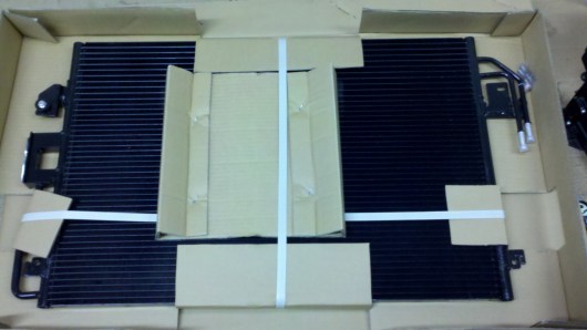
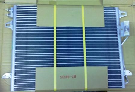
Over the last decade, engineers at Chrysler, Ford, and some of the import vehicle manufacturers have released several designs which eliminate the oil cooler in the radiator tank and instead integrate the transmission oil cooling and the air conditioning condenser functions into a common heat exchanger.  Sometimes they also integrate the power steering cooler providing three separate circuits in one heat exchanger assembly.  This arrangement is more compact, lighter weight, and lower cost than previous configurations.

Ford Escape Condenser with Integrated Transmission Oil Cooler

Chrysler Minivan Condenser with Integrated Oil Cooler

A few of the integrated designs include a thermostatic or pressure regulated valve to allow cold – high viscosity transmission fluid to by-pass the heat exchanger.  The 2006 Ford Crown Victoria uses one of these valves.

Ford Crown Victoria Condenser with Integrated Oil Cooler

The transmission oil cooler lines may be connected with rubber hoses and clamps, as in the Ford Escape arrangement, but often they use standard quick connect fittings like those used on the Chrysler Minivan. 

There would not be any special service considerations for these integrated oil coolers if not for the fact that the air conditioning system must be evacuated and recharged if the oil cooler fails, or is damaged, and must be replaced.  Shops performing this repair work must therefore have AC certified technicians and refrigerant recovery – recharge equipment.

http://macsworldwide.wordpress.com/


http://macsworldwide.wordpress.com/.

Oil Cooler Connections – Ford Truck & Cadillac CTS


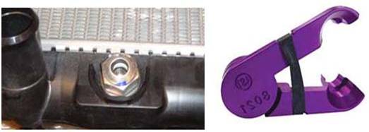
In our last tech tip article we reviewed the Jiffy-Tite® connector design which General Motors engineers started to use in some applications in 1996.  While most GM vehicles use Jiffy-Tite® connectors today, the exception is on some of the Cadillac platforms.  The 2003 Cadillac CTS introduced a new low profile quick connect which has proved troublesome to many technicians who see it for the first time.  The new quick connect design used on several Cadillac models is similar to that also used on 2003 Ford Explorer and F-150 models.  See photos below for details of the new connector design as applied on some Ford applications.

Ford Oil Cooler Quick connect and Dis-connect tool

Most mechanics use common tools like the one shown in the above photo to separate the Ford connections but because of the tight bend radius on the tube side of the Cadillac oil cooler lines the common disconnect tool will not fit. The tool shown below is designed for applications like the Cadillac CTS.  When a low profile tool is not available the standard tools have to be modified by grinding away a portion of the collar.

Cadillac CTS Oil Cooler Quick Connect and Disconnect Tool

As discussed in the last Tech Tip, the Cadillac application uses an integrated quick connect design to not only make the connection between the oil cooler and the line but also to secure the oil cooler in the radiator tank.  These fittings are not intended to be disturbed once the radiator leaves the factory. 

Cadillac CTS Oil Cooler Quick Connect and Fitting Removed
 
Loosening the integrated fittings compromises the factory seal between the oil cooler and the radiator tank and the joint cannot be reliably repaired.  If a technician removes the oil cooler fitting from a new radiator in most all cases the radiator must be scrapped.