Category Archives: Radiator

Oil Cooler Connections – Ford Truck & Cadillac CTS


In our last tech tip article we reviewed the Jiffy-Tite® connector design which General Motors engineers started to use in some applications in 1996.  While most GM vehicles use Jiffy-Tite® connectors today, the exception is on some of the Cadillac platforms.  The 2003 Cadillac CTS introduced a new low profile quick connect which has proved troublesome to many technicians who see it for the first time.  The new quick connect design used on several Cadillac models is similar to that also used on 2003 Ford Explorer and F-150 models.  See photos below for details of the new connector design as applied on some Ford applications.

Ford Oil Cooler Quick connect and Dis-connect tool

Most mechanics use common tools like the one shown in the above photo to separate the Ford connections but because of the tight bend radius on the tube side of the Cadillac oil cooler lines the common disconnect tool will not fit. The tool shown below is designed for applications like the Cadillac CTS.  When a low profile tool is not available the standard tools have to be modified by grinding away a portion of the collar.

Cadillac CTS Oil Cooler Quick Connect and Disconnect Tool

As discussed in the last Tech Tip, the Cadillac application uses an integrated quick connect design to not only make the connection between the oil cooler and the line but also to secure the oil cooler in the radiator tank.  These fittings are not intended to be disturbed once the radiator leaves the factory. 

Cadillac CTS Oil Cooler Quick Connect and Fitting Removed
 
Loosening the integrated fittings compromises the factory seal between the oil cooler and the radiator tank and the joint cannot be reliably repaired.  If a technician removes the oil cooler fitting from a new radiator in most all cases the radiator must be scrapped.
 

Oil Cooler Connections – GM Quick Connects


In our first two tech tip articles we reviewed radiator cap functions and application considerations.  The next few articles will cover the different types of “Quick Connects” used by original equipment manufacturers to attach transmission and engine oil cooler lines to the heat exchangers in the power train cooling system.  In this particular article we will review the Jiffy-Tite® connector design which General Motors engineers started to use in some applications in 1996.  Most GM vehicles use Jiffy-Tite® connectors today, the exception being some of the Cadillac platforms.

Until the middle 90’s most oil coolers were connected to the oil lines using rubber hose and clamp or inverted flare joint designs.  See photo of rubber hose type connection and sketch of inverted flare joint below.

Rubber hose and clamp fitting  

Inverted flare connetion 


Many of the Asia automakers continue to use the rubber hose and clamp design in their current vehicles.  Each of these conventional joint designs has their own merits and disadvantages.  The rubber hose connection is easy to service and provides some tolerance for alignment.  One disadvantage is that sealing is affected by changes in clamping force as the rubber hardness varies with temperature and takes a compression set with age.

Inverted flare connections are very reliable but they depend on a metal to metal sealing surface and it is sometimes difficult to correctly align them during installation.  To seal effectively, one or both sides of the joint surface must be forced to conform to the other as the joint is tightened.  As parts become contaminated with corrosion and dirt it becomes even more difficult to effect leak proof connections. 

In many applications, steel lines and fittings are being jointed to brass or aluminum oil coolers.  When leaks occur at these joints the first repair attempt often results in over-tightening and stripping of the threads on the oil cooler connector.  Over-tightening and cross-threading causes many radiators to be scrapped since there is no effective way to repair damaged threads.  Over-tightening can also cause damage to the oil cooler inside the radiator tank where a leak will lead to mixing of oil and coolant.

Some aftermarket suppliers supply small o-rings to place in the interface between the male and female connections.  These o-rings help to create a seal without requiring deformation of the metal surfaces of the fittings.  See sketch below.

Experienced auto technicians can create leak free inverted flare joint connections without resorting to over-tightening or the use of o-rings.  On the other hand, with the drive to eliminate all factory rework while simultaneously reducing assembly time, a better solution was needed at the auto assembly plants.  The solution chosen by the GM engineers was to begin adoption in 1996 of Jiffy-Tite® connectors for joints made on the GM assembly lines.  Except for a few applications which use radiators and oil coolers produced by Denso, the Jiffy-Tite® connector has become a standard in GM applications and is also used in many Mercedes, Chrysler, and other applications.

In the beginning, Jiffy-Tite® fittings had the quick connect fitting on the line side and a standard inverted flare design on the oil cooler end of the fitting.  Subsequent designs use o-ring or seal washer designs on the oil cooler side.  See photos below.

In many later model radiator applications an integrated Jiffy-Tite® design is used to not only make the connection between the oil cooler and the line but also to secure the oil cooler in the radiator tank.  It is these later designs that prove most troublesome in the field.  These fittings are not intended to be disturbed once the radiator leaves the factory.  Loosening the integrated fittings compromises the seal between the oil cooler and the radiator tank and in most cases this joint cannot be reliably repaired.  See photos below.


To remove the oil line from a Jiffy-Tite® connector first slide back the plastic cover (if present) and then use the appropriate tool to open the legs of the retaining clips.  Once the legs are open the line may be pulled out of the fitting.  If a tool is not available to open the legs then a small screwdriver can be used to completely remove the clip from the fitting.  See photos below.

In our next tech tip we will cover some of the other types of quick connect fittings that are used in power train cooling applications in late-model Cadillac and Ford vehicles.

Radiator Caps – (continued)


In our first tech tip on radiator caps we reviewed the functions of the cap, the basic construction of a typical cap, and why one should inspect and test or replace the radiator cap when performing cooling system maintenance.  In this article we will review some of the application considerations that are important when choosing the correct replacement cap.

The three key characteristics for standard metal radiators caps are:

  1. Size – Large, Medium, Small, Mini, Micro
  2. Release Pressure
  3. Siphon (Vacuum) Pressure

Large size caps are used for off-highway and industrial applications which require a large volume of coolant and fast fill rates.  Medium caps are standard on most large truck applications.  Small caps are standard on most domestic applications, light trucks and cars alike, from the 60’s through today.  Mini caps are used on some smaller domestic applications and mini or micro caps are standard on most imports.  Micro caps, also called Denso style caps, are standard on import applications where the OEM radiator was manufactured by Denso – Toyota, Honda, Acura, Subaru, and others.
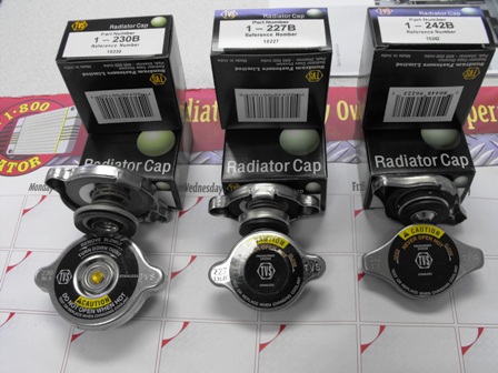
 Small Cap                         Mini Cap                      Micro Cap

 Cap release pressures for original equipment applications can range from 7 PSI up to 30 PSI, with the latter being many European applications.  Many late model domestic applications are now using operating pressures in the 18-20 PSI range.

Installing a cap with too low of a pressure rating can cause coolant loss, loss of coolant circulation because of pump cavitation, overheating, and engine damage.  Installing a cap with too high a pressure rating may overstress the radiator, hoses, seals and other cooling system parts also leading to loss of coolant, overheating and engine damage.

Some radiator cap vacuum relief (siphon) valves are spring loaded to keep them normally closed and others rely on the coolant pressure to hold them closed.  In a closed type engine cooling system, coolant expansion forces air and coolant past the radiator cap into an open reservoir for deareation and storage.  When the coolant in the engine and radiator returns to ambient temperature and contracts, the vacuum created siphons coolant from the reservoir tank through the radiator cap relief valve back into the radiator.  Systems which use remote pressurized systems may have caps located somewhere in the system that do not have a relief valve.

A relief valve that fails to seal properly will cause over-heating problems just like a cap with too low of a pressure rating.  If the valve fails to open then the vacuum created when the coolant contracts can collapse coolant hoses or cause air to be drawn into the system.  Installing a new cap with the wrong type of relief valve will also cause performance and reliability issues so always confirm not only the pressure but also the relief specifications before simply choosing a cap that fits the filler neck.

 One of the most common application issues encountered relates to confusion between the “mini” and “micro” size caps.  The caps may appear to be interchangeable but neither will work on filler necks designed for the other.  Some aftermarket radiator manufacturers choose to use the mini cap and filler neck design to replace the micro design used on the original equipment radiator.  When servicing late model Honda/Acura applications that may have OE radiators sourced from two different manufacturers the cap and filler neck designs will also be different.  In an effort to reduce costs in the aftermarket offerings, most vendors will build their radiator to accept only the micro or Denso style cap.  But if the vehicle has an aftermarket replacement radiator in it already, there is a risk that the old cap will not fit the new replacement radiator.  Please refer to the picture below for differences between the two caps.
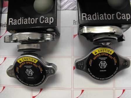
 

Mini Cap                                                   Micro Cap

 The easiest way to distinguish between the mini cap on the left and micro cap on the right is to compare the top of the cap.  The mini cap ears have rounded corners and the micro cap ears have more square corners.  The functional difference relates to the depth from the upper sealing surface to the lower sealing surface but this is harder to recognize unless you have the two types of caps side by side to compare.  It is even harder to look at the radiator filler neck and recognize which cap is needed.

 In summary, always use replacement caps with the same release and vacuum pressures as the original equipment cap.  And while there are rarely application issues with the standard “small” caps, there can be problems when servicing an OE or aftermarket radiator that incorporates the “mini” or “micro” cap design.  In these cases, to select the correct cap, one needs to consider not only the pressures but also the filler neck design of the radiator.

Radiator Caps


Radiator caps are relatively simple in appearance but they are extremely important components of the engine cooling system.  Like radiators and other cooling system parts they are exposed to harsh environments while functioning relatively maintenance free for several years and many miles of service.  But the metal, plastic, and especially the rubber materials in radiator caps will deteriorate or become contaminated over time.  Therefore, radiator caps should always be inspected and tested carefully whenever performing cooling system maintenance.

 The radiator pressure cap serves five important functions in the cooling system.

  1. Filler cap to access the cooling system
  2. Closure cap to keep coolant in the radiator 
  3. Pressure cap to prevent overheating by maintaining system pressure to raise the boiling temperature of the coolant thereby allowing the engine to operate at more efficient higher temperatures.  The higher operating pressures also provide a margin of safety at the water pump inlet to prevent damaging cavitation which can lead to loss of coolant circulation and/or pump impeller erosion.
  4. Pressure relief valve to safely and harmlessly vent excess coolant and air into the overflow reservoir as the coolant expands when it is heated.  By preventing excessive internal pressure it protects the radiator and other cooling system components.  The pressure relief valve functions in conjunction with the vacuum relief valve to facilitate the removal of air from the cooling system after the initial factory fill and after cooling system service.  Entrained air needs must be purged from the cooling system to maximize cooling performance and to control internal corrosion of the engine and the radiator.
  5. Vacuum relief/siphon valve to allow coolant to return from the overflow reservoir back into the radiator.  When the coolant in the hot system returns to ambient temperature it contracts creating a vacuum which draws coolant back through the valve and into the system from the overflow reservoir.

There are several components in the radiator cap that must work in harmony for the cap to function properly.  The parts in a conventional radiator cap are illustrated in the diagram shown below.

Two of the most important components are the two elastomeric seals (gaskets) that mate with features in the radiator filler neck to either contain the coolant under pressure or direct coolant to and from the overflow reservoir.  The lower gasket provides a seal between the pressure valve and the radiator filler neck and also between the radiator cap vacuum valve and the pressure valve.  The upper seal assures that pressurized coolant is directed through the overflow tube on the filler neck when it is released past the lower seal.  If either of these seals are compromised due to age or by corrosion product contamination then the 5 radiator caps functions noted above will be affected.

While the radiator cap is a relatively inexpensive component of the cooling system its proper operations is critical to the efficient and reliable operation of the entire power train system.   Most service experts believe that replacing the old radiator cap is inexpensive insurance when performing cooling system maintenance and always recommend a new cap whenever a new radiator is installed.  At a minimum the cap should be inspected and tested for proper sealing and pressure release functions when a new radiator is installed and when the coolant is changed.

Some of the domestic and foreign original equipment manufacturers are now choosing caps made of plastic components over the more conventional caps made from stamped metal components.  But regardless of the design, all caps use elastomeric seals which are subject to aging from heat, chemical, and ozone exposure.   So while the plastic parts may still look good, the working components may have past their useful life expectancy and the cap assembly should be replaced.  Again, inspect and test, or install a new cap as cheap insurance when performing routine maintenance or repairs.

Look for more application information and service tips about radiator caps in our next installment of “Keeping it Cool Tech Tips”.